


Circuits
Key Ideas
The current in series resistors is the same through each, whereas the voltage across series resistors adds to the total voltage.
The voltage across parallel resistors is the same across each, whereas the current through parallel resistors adds to the total current. T
The brightness of a light bulb depends on the power dissipated by the bulb.
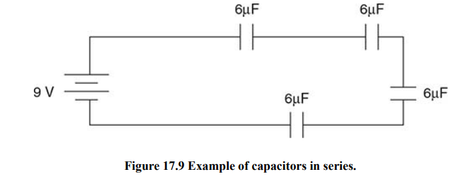
A capacitor blocks current once it has been connected for a while.
Current
Current: The flow of electric charge.
In a circuit, the current is the amount of charge passing a given point per unit of time.
Resistance and Ohm’s Law
The reason most circuits contain a battery is that batteries create a potential difference between one end of the circuit and the other.
Positive charge flows from high potential to low potential.
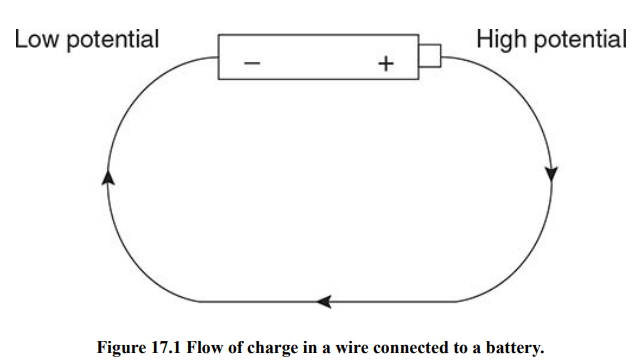
The greater the potential difference between the terminals of the battery, the more current flows.
The amount of current that flows in a circuit is also determined by the resistance of the circuit.
Resistance: A property of a circuit that resists the flow of current.
Resistance is measured in ohms. One ohm is abbreviated as 1 Ω.
If we have some length of wire, then the resistance of that wire can be calculated.
Three physical properties of the wire affect its resistance:
The material the wire is made out of the resistivity, ρ, of a material is an intrinsic property of that material. Good conducting materials, like gold, have low resistivities.
The length of the wire, L: the longer the wire, the more resistance it has.
The cross-sectional area A of the wire: the wider the wire, the less resistance it has.
Resistor: Something you put in a circuit to change the circuit’s resistance.
Resistors are typically ceramic, a material that doesn’t allow current to flow through it very easily. Another common type of resistor is the filament in a light bulb.
When current flows into a light bulb, it gets held up in the filament.
While it’s hanging out in the filament, it makes the filament extremely hot, and the filament gives off light.
Ohm’s Law: V = IR.
V is the voltage across the part of the circuit
I is the current flowing through that part of the circuit
R is the resistance in that part of the circuit.
When current flows through a resistor, electrical energy is converted into heat energy. The rate at which this conversion occurs is called the power dissipated by a resistor. This power can be found with the equation:
P = IV.
Power, P, dissipated in part of a circuit equals the current flowing through that part of the circuit multiplied by the voltage across that part of the circuit.
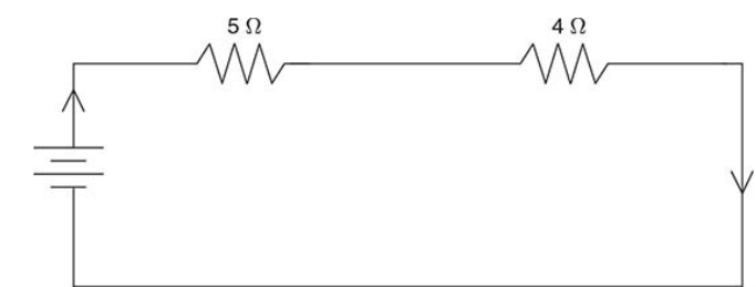
Resistors in Series and in Parallel
In a circuit, resistors can either be arranged in series with one another or parallel to one another.

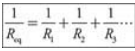
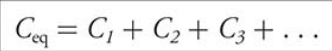
To find the equivalent resistance of series resistors, add up all the individual resistors.
Parallel resistors are connected in such a way that several paths are created through which current can flow.
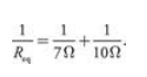
For the resistors to be truly in parallel, the current must split, then immediately come back together. The equivalent resistance of parallel resistors is found by this formula:
A Couple of Important Rules
Rule #1: When two resistors are connected in SERIES, the amount of current that flows through one resistor equals the amount of current that flows through the other resistor.
Rule #2: When two resistors are connected in PARALLEL, the voltage across one resistor is the same as the voltage across the other resistor, and is equal to the total voltage across the parallel combination.
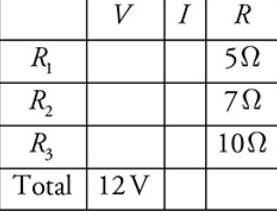
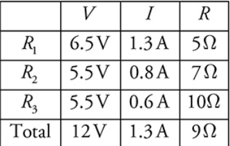
The V-I-R Chart 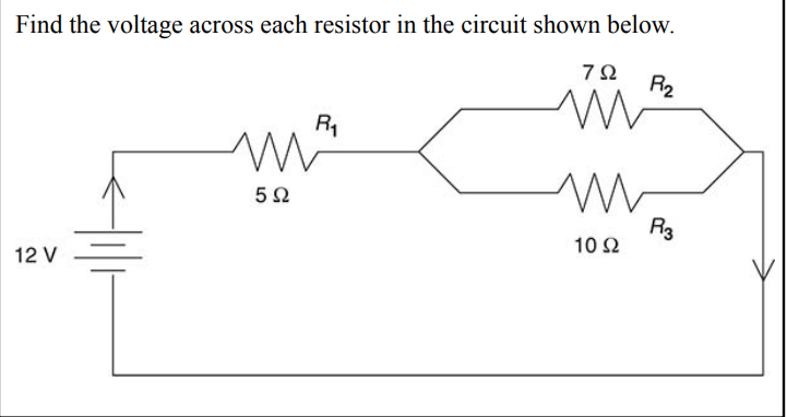
Draw the V-I-R chart the following way
Next, simplify the circuit by calculating the equivalent resistance and redraw the circuit accordingly.
![]()
Redraw the circuit the following way
Next, we calculate the equivalent resistance of the entire circuit. Then fill the value again in the chart.
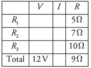
Using Ohm’s law, we can calculate the third.
Ohm’s law is valid whenever two of the three entries in a row are known.
the I value in the “R 1” row will be the same as the I in the “Total” row.
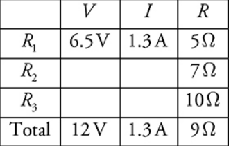
The voltage across R 2 equals the voltage across R 3 , because these resistors are connected in parallel. The total voltage across the circuit is 12 V, and the voltage across R 1 is 6.5 V.
Therefore, the voltage across R 2 , which is the same as the voltage across R 3 , is 5.5 V. We can fill this value into our table
The finished V-I-R chart is as follows
Kirchoff’s Laws
Kirchoff’s laws help you solve complicated circuits. They are especially useful if the circuit contains two batteries.
Kirchoff’s laws say:
Junction rule - At any junction, the current entering equals the current leaving.
Loop rule -The sum of voltages around a closed loop is 0.
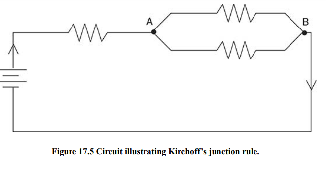
Kirchoff’s junction rule says that charge is conserved: you don’t lose any current when the wire bends or branches.
Arbitrarily choose a direction of the current.
Draw arrows on your circuit to indicate this direction.
Follow the loop in the direction you chose. When you cross a resistor, the voltage is -IR, where R is the resistance, and I is the current flowing through the resistor. This is just an application of Ohm’s law.
When you cross a battery, if you trace from the - to the + add the voltage of the battery, and subtract the battery’s voltage if you trace from + to -.
Set the sum of your voltages equal to 0. Solve. If the current you calculate is negative, then the direction you chose was wrong—the current actually flows in the direction opposite to your arrows.
Circuits from an Experimental Point of View
Brightness of a Bulb
The brightness of a bulb depends solely on the power dissipated by the bulb
Ammeters and Voltmeters
Ammeters measure current, and voltmeters measure voltage.
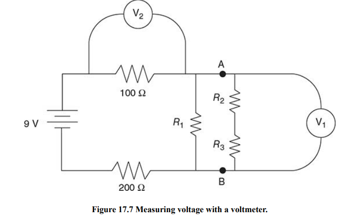
Current is the same for any resistors in series with one another.
To measure the current through a resistor, the ammeter must be in series with that resistor.
RC Circuits: Steady-State Behavior
When you have both resistors and capacitors in a circuit, the circuit is called an “RC circuit”.
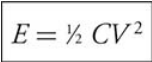
Energy stored in capacitor
Once the circuit has been connected for a long time, capacitors stop current from flowing.
RC Circuits: Transitional Behavior
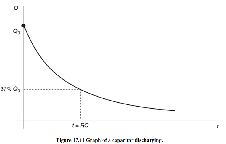
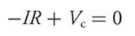
Apply Kirchoff’s voltage rule:
Vc is the voltage across the capacitor, equal to Q/C by the equation for capacitors.
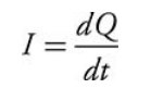
Current is the time derivative of charge.
Inductors in Circuits
An inductor makes use of induced EMF to resist changes in current in a circuit.
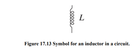
The voltage drop across an inductor is
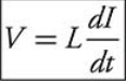
L is called the inductance of the inductor.
Inductance is measured in units of henrys.
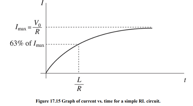
If the current is changing rapidly, as when a circuit is first turned on or off, the voltage drop across the inductor is large;
If the current is barely changing, as when a circuit has been on for a long time, the inductor’s voltage drop is small.
Other Circuits
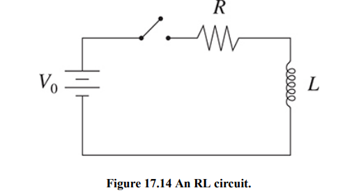
RL Circuits
RL circuits contain just an inductor and a resistor, and perhaps a battery.
LC Circuits
In a circuit consisting of just a capacitor and an inductor, both the capacitor and inductor try to store energy.