Resistance and V=IR
There’s a formula linking Potential Difference and Current
Potential Difference=Current x Resistance
You can investigate the factors affecting resistance:
The resistance of a circuit can depend on a number of factors, like whether components are in series or parallel, or the length of wire used in the circuit. You can investigate the effect of wire length using the circuit:
The Ammeter: Measures the current flowing through the test wire. The ammeter must always be placed in series with whatever you’re investigating
The Voltmeter: Measures the potential difference across the test wire. The voltmeter must always be placed in parallel around whatever you’re investigating, NOT around the other bit of the circuit.
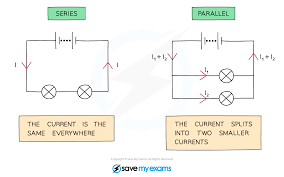
There can be parallel or series circuits
Measuring the length of wire per resistance:
Attach a crocodile clip to the wire level with 0cm on the ruler
Attach the second crocodile clip to the wire. Write down the length of the wire between the clips
Close the switch, then record the current through the wire and the pd across it
Open the switch then move the second crocodile clip. Close the switch again, then record the new length, current and pd
Repeat this for a number of different lengths of the test wire
Use your measurements of current and pd to calculate the resistance for each length of wire, using R=V/I
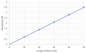
Plot a graph of resistance against wire length and draw a line of best fit
Your graph should be a straight line through the origin, meaning resistance is directly proportional to length-the longer the wire, the greater the resistance
If your graph doesn’t go through the origin, it could be because the first clip isn’t attached exactly at 0cm, so all of your length readings are a bit out