Chapter 9: Magnets and Currents
Magnets
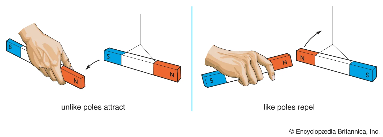
Magnetic Poles
North seeking pole - N pole
South seeking pole - S pole
Like poles repel; unlike poles attract.
The closer the poles, the greater the force between them.
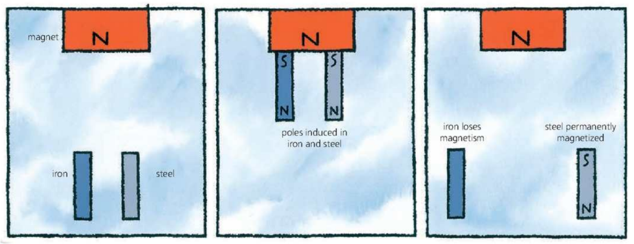
Induced Magnets
Magnetic and Non-magnetic Materials
Magnetic Materials - is one which can be magnetized and is attracted to magnets.
All strongly magnetic materials have iron, nickel or cobalt.
Strongly magnetic are called ferromagnetic.
Hard Magnetic Materials - such as steel, and alloys called Alcomox and Magnadur, are difficult to magnetize but do not readily lose magnetism. They are used for permanent magnets.
Soft Magnetic Materials - such as iron or mumetal are relatively easy to magnetize, but their magnet is temporary.
They are used in electromagnets; because their magnetic effect can be switched ‘‘on’’ and “off”.
Non-magnetic Materials - include metals such as brass, copper, zinc, tin, and aluminum as well as non-metals.
Magnetic Effect a Current
Magnetic Field around a Wire
If an electric current is passed through a wire, as shown below, a weak magnetic field is produced. The field is produced. The field has these features:
the magnetic field lines are circles
the field is strongest close to the wire
increasing the current increases the strength of field
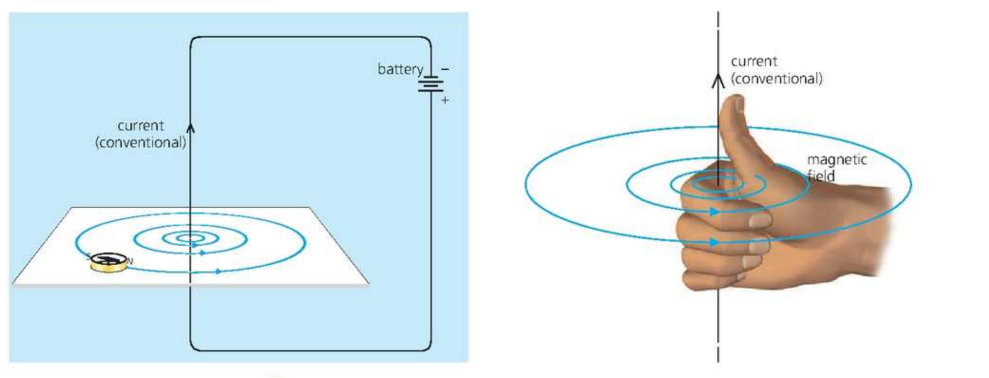 A rule:
The direction of the magnetic field produced by the current is given by the right hand rule (shown above). Imagine gripping the wire with your hand so that your thumb points in the conventional current direction. Your fingers then point in the same direction as the field lines.
Magnetic field from coils
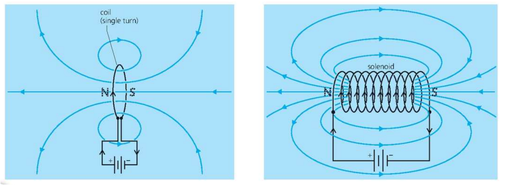
The magnetic field produced by a current carrying coil has these features:
The field is similar to that from a bar, and there are magnet poles at the end of coil
Increasing the current increases the strength of the field
Increasing the number of turns on the coil increases the strength of field
Electromagnets
The strength of the magnetic field is increased by:
increasing the current
increasing the number of turns in the coil
Reversing the current reverses the direction of the magnetic field.
Uses of Electromagnets
Go through the following website:
https://spark.iop.org/electromagnets-everyday-use
Magnetic on a Current
The force is increased if:
the current is increased
if stronger magnets are used
the length of the wire in the field is increased.
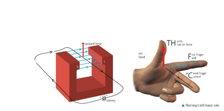
Fleming’s Left Hand Rule
Direction of force can be predicted.
In applying the rule, it is important to remember how the field and current directions are defined by:
the field direction is from N pole of a magnet to S pole.
the current direction is from the positive (+) terminal of a battery round to the negative (-). This is called conventional current direction.
If a beam of charged particles pass through a magnetic field, there is a force on it, just as for the current in a wire.
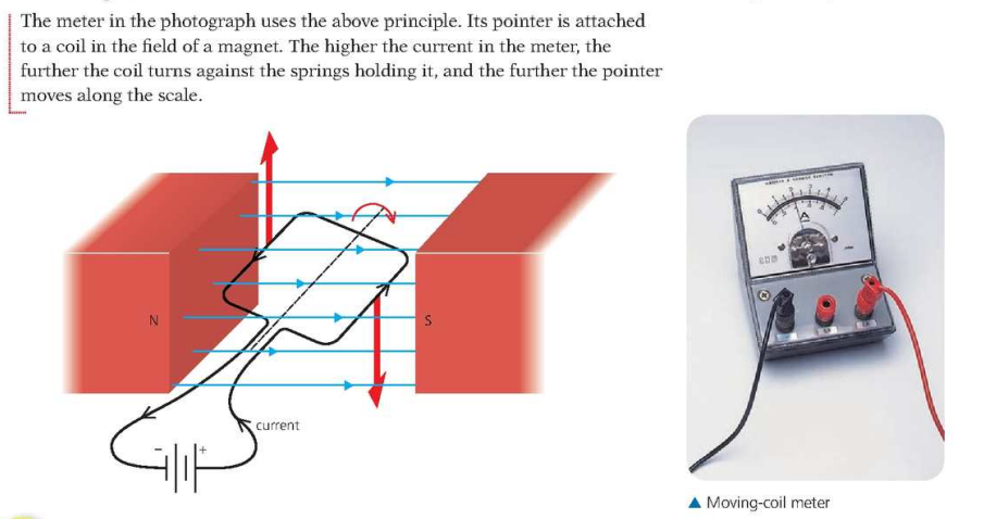
Turning Effect of a Coil
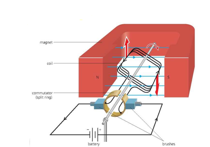
Electric Motors
A D.C motor
Watch the following videos:
Turning effect on the coil can be increased by:
increasing the current
using a stronger magnets
increasing the number of turns on the coil
increasing the area of the coil
Increased Induction
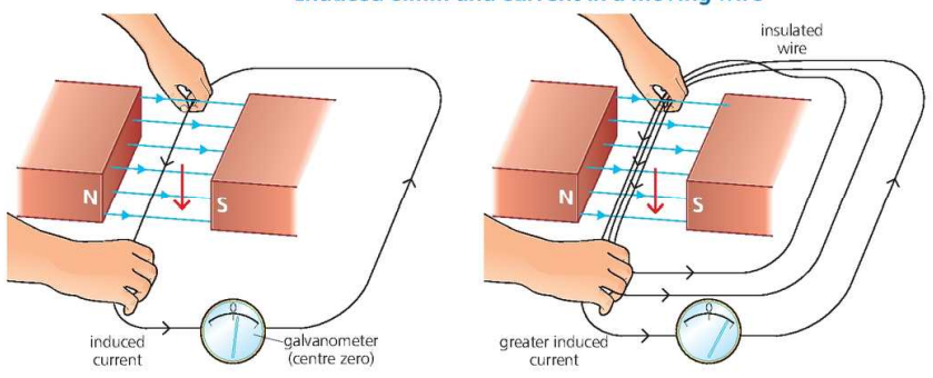
When a wire is moved across a magnetic field, a small voltage is generated in the wire. This effect is called electromagnetic induction.
The emf (electromotive forces) or current is increased by:
moving the faster
using a stronger the magnet
increasing the length of the wire in the magnetic field.
The emf induced in a conductor is proportional to the rate at which magnetic field lines are cut by the conductor.
Following will reverse the direction of the induced voltage and current:
moving the wire in the opposite direction
turning the magnet round so that the field direction is reversed.
Induced emf and current in the coil
If a bar magnet is pushed into a coil, and emf is induced in the coil. As shown below.
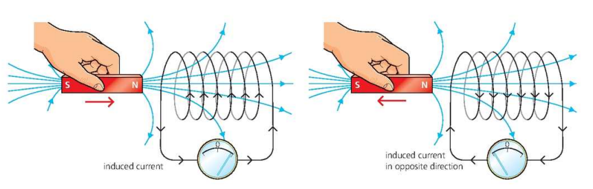
In this case, it is the magnetic field that is moving rather than the wire, but the result is the same: field lines are being cut.
The induced emf can be increased by:
moving the magnet faster
using a stronger magnet
increasing the number of turns on the coil
If the magnet is pulled out of the coil, the direction of the induced emf and current ir reversed.
If the S pole of the magnet, rather than the N pole, is pushed in the coil, this also reverses the current direction.
If the magnet is held still, no field lines are cut, so there is no induced emf or current.
Lenz’s Law
It states that and induced current always flows in a direction such that it opposes the change which produced it.
Fleming’s Right Hand Rule
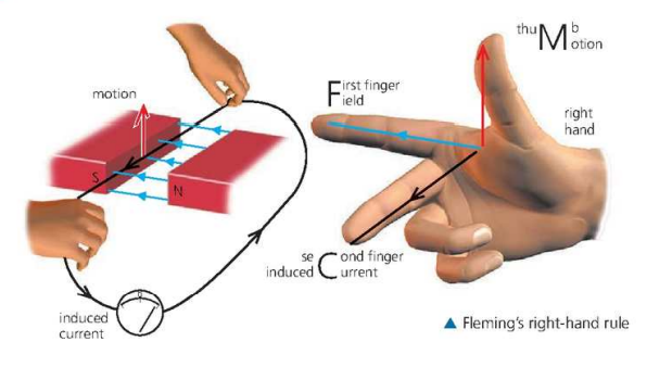
POINTS TO KEEP IN MIND FOLLOWING RIGHT AND LEFT HAND RULE:
when a current causes motion, left hand rule applies.
when motion causes a current, the right hand rule applies.
For a better understanding of the concept watch the following video:
Generators
AC Generator
Alternating Current
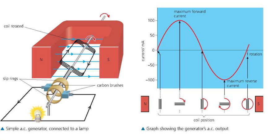
When current is passed, the rectangular coil rotates between poles of magnet, due to magnetic force. According to fleming’s left hand rule, on left hand side force acts upwards and on right hand side force acts downwards. These forces being equal in magnitude, but opposite in direction rotate coil in same direction.
Coils and Transformers
Mutual Induction
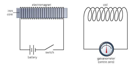
As the galvanometer is switched on, an emf induced in the other coil, but only for a fraction of a second. The effect is equivalent to pushing a magnet towards a coil very fast
The induced emf at switch on or switch off is increased if:
the core of the electromagnet goes right through the second coil
the number of turns on the second coil is increased.
Transformer
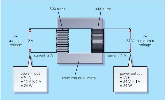
AC voltage can be increased or decreased using a transformer.
When alternating current flows in the primary (input) coil, it sets up an alternating magnetic filed in the core and therefore, in the secondary (output) coil.
This changing field induces an alternating voltage in the output coil.
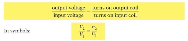
Provided all the field lines pass through both coils, and the coils waste no energy because of heating effects, the following equation applies:
Step up and Step down transformers
A transformer can increase or decrease an AC voltage:
Step up transformer have more turns on the output coil than on the input coil, so their output voltage is more than the input voltage. The transformer in the diagram below is a step-up transformer. Large step-up transformers are used in power stations to increase the voltage to the levels needed for overhead power lines. The next spread explains why.
Step-down transformers have fewer turns on the output coil than on the input coil, so the output voltage is less than the input voltage. In battery chargers, computers, and other electronic equipment, they reduce the voltage of the a.c. mains to the much lower levels needed for other circuits.
Through the following equation we can calculate power supply through a transformer:
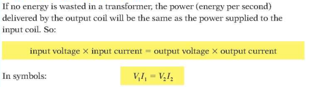
Following is the method to use the above equation: