


Electricity
Circuits Introduction
A circuit is closed loop with a power source and something for electrons to flow through.
Battery are made up of 2 or more cells, act in the same way as a cells, a filament lamp is a small light bulb.
Current is a measure of the flow of electrons around the circuit, measured in Amps (A)(I)
Potential Difference is the force driving the flow of electrons, provided by cell/battery measured in Volts (V)
Resistance is everything that resists of opposes the flow of electrons, measured in Ohms (?) (R)
Cell long line is the positive terminal, short line is the negative terminal. Electrons travel from Negative to positive terminal, however scientist originally thought it went from positive to negative- which is called the conventional current. Current always flows from the positive to the negative terminals.
V=IR Equation & I-V Graphs
Current Potential Difference
Potential difference is equal to current multiples by resistance- V=IR.
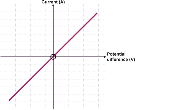
If the resistance is constant, when the voltage increases the current should increase proportionally. This is could be done with a bigger battery (increase in voltage), the current also increases.
The bottom region is the same but the battery is attached the opposite way, making the results negative.
This happens in circuits with only wire or resistors.
By using a diffrent resistor the line becomes more/less steep. A bigger resistor would have a less steep line and a smaller would have a steeper line. It shows how much potential difference is required to produce a current.
For example, a smaller resistor and less overall resistance would need a small voltage to drive a large current.
This happens if the temperature is constant, If the temperature increases the resistance would also.
As temperature increases, all of the ions in the metal vibrate faster, which makes it harder for electrons to pass along the wire
Higher currents lead to higher temperatures so lines aren’t so straight.
Filament Lamp
Filament Lamps are lamps that contain filament that heat up until it so hot that it emits light, which increases the resistance.
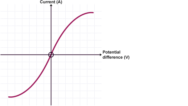
As the current increases, the curve becomes less steep. Which shows less current can flow per unit of potential differences at higher voltages. The temperature and resistance is so much higher.
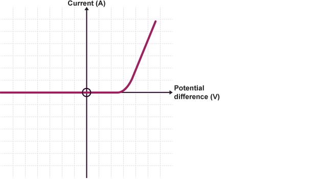
Diodes
Diodes only allow current to flow in one direction which is why they only show a current when potential difference is positive.
They have a very high resistance in the reverse direction, so no current can flow in that direction**.**
Charge,Current and Time
Charge is a measure of the total current that flowed within a certain period of time (Q)/ (Colombs).
Charge equals current multipled by time- Q=It
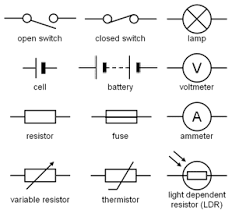
Components
Uses of Components
Cells and Batteries are used to provide electric power.
Switches are used to control the flow of electricity.
Fuses are used to break if too much current flows through the circuit.
Diodes which only allow current to flow in one direction.
Light-Emmitting Diode (LED) are emits light when current flows through in a forward direction
Meters
Ammeters are used to measure current, connected in a series circuits.
Voltmeters are used to measure potential difference, connected in parallel circuits.
Resistors
Fixed resistors provided a certain number of ohms.
Variable resistors are easily modified to an amount of resistance.
Light-Dependent Resistors resistance is dependent on the intensity of light, in (bright) light there is low resistance so lots of current can flow. In darkness there is high resistance so hardly any current can flow,
They can be used in things such as automatic night-lights and Burglar alarms.
Thermistors resistance is dependent on the temperature, so higher temperatures cause low resistance and low temperatures cause high resistance.
They can be used in temperature receptors in things like car engines and electronic thermostats.
Series Circuits
A single loop with connected components, if broken or disconnected the whole circuit stop working.
Potential Difference
The potential difference of the battery is shared across all of the components. Total V= V1+V2+V3
In a series circuit the total resistance is equal to the sum of the individual resistances of each component.
Current is the same everywhere in the circuit measured by an ammeter
Resistance
Total resistance is the sum of individual resistances of each components. Ammeters have tiny resistances so they are ignored. Voltmeter are connected in parallel but the circuit is considered as series.
Components with a greater resistance, will always have a higher share of the voltage- more force is required to push the charge through the areas of highest resistance.
Parallel Circuits
More than one loop, each loop has a single component. When one breaks, the overall circuit is still intact.
Potential Difference
All the components in a parallel circuit have the same potential difference. All of the components get their full source of potential difference. Vtotal= V1=V2= V3
Current is shared throughout all of the loops. Itotal= I1+I2+I3
The way the current splits depends on the resistance of individual components in the circuit. Loops that have greater resistance taking a lower share of the current.
Resistance
The more components in parallel the lower the total resistance, the more loops the lower the resistance.
Adding a resistor in a parallel with an existing resistor will decrease the overall resistance.
Energy and Power Formulas
Energy Formulas
Energy (E)= Power (P) x Time (t) E=Pt
Energy (E)= Voltage (V) x Current (I) x Time (t) E=VIt
Energy (E)= Charge (Q) x Voltage (V) E=QV
Power Formulas
Power (P) = Current (I) x Voltage (V) P=IV
Power (P) = (Current x Current (I)) x Resistance (R) P=IxIxR
National Grid
The National Grid is a giant network that distributes electricity for the UK, mostly coming from power stations.
Power stations generate loads of heat and converting the thermal energy into electrical energy, which depends on demand. This peaks later in the afternoon, so they run below their maximum power output.
National grid has to transmit huge amounts of power, but with high current lots of heat is produced because of the resistance so lots of energy could be lost into the surroundings. To stop this, the current is low and voltage is high.
The electricity from the power station has increased voltage before sending it across to the country, we use Step-Up Transformers which increase the voltage to 400,000 V.
Wires of Pylons transmit the energy to Step-Down transformers which reduce the voltage to 230V, this is because high voltages are dangerous and would blow appliances.
As temperature increases, all of the ions in the metal vibrate faster, which makes it harder for electrons to pass along the wire (or in other words, the resistance increases).
Step-Up Transformers increase voltage to minimise energy loss during transmission and decrease current to minimises power loss.
Step-Down Transformers decrease voltage to make it safe to use and increase current.
Fossil Fuel and Nuclear Power
Fossil fuel and nuclear power stations work by generating thermal energy. This is used to turn water into steam which can then rise and turn turbines.
The kinetic energy of the moving turbines can be converted to electrical energy, which is finally sent out across the national grid.
AC and DC Current
Alternating Current
Alternating Current is constantly swapping directions, this happens when we use an alternating potential difference which fluctuates between positive and negative current/voltage. In a circuit the direction of charge is flowing back and forth.
Mains supply is the electricity coming from the plug sockets is an Alternating current which is 50 Hz and 230 V. This means that the rate at which potential difference and current fluctuates is from +230V to -230V, 50 times per second
Direct Current
Direct current either has a positive or negative potential difference/current. The charge is always flowing in the same direction. Direct Current is used in Cells and Batteries.
To measure how voltage changes with time we use oscilloscopes, which display the graphs on a monitor.
Plugs & Wires
Mains supply comes from the National Grid, so when an object is plugged in it uses a Three-Core Cable. They are made of copper to conduct electricity and coated in a layer of insulating plastic for safety. The difference in the wires voltage causes electricity to pass from one to the other. Because humans have 0V, by touching something with high voltages it would cause it flow through us- electric shock
Earth
It is Green and Yellow which doesn’t carry a current or potential difference. This stops the appliance casing from becoming live (big electric shocks) by providing an alternative pathway for current to flow.
Live
It is the brown wire which provides the alternating potential difference/current from the mains supply.
Neutral
It is the blue wire which completes the circuit by carrying away current. It has a potential difference of OV
Fuses & Earthing
Surges are sudden increases in current, which happen when either an appliance is turned on or off or there is a fault in the circuit or appliance. They can result in damage to the appliance, fires or electric shocks. To stop there are safety precautions like Fuses, Earth wires, Double Insulation or Circuit Breakers.
Fuses
They are used to break the circuit whenever there’s a surge, it is a thin piece of wire connected to the live wire. When there’s a surge lots of current flow through the fuse and current so it heats up fast and melts- breaking the current so no more current can flow.
Fuses are sold in different ratings by the current wanted to break the circuit, for example a 3A appliance would have a 5A fuse.
Fuses are simple and cheap but need to be replaced every surge as they are permanently broken.
Circuit Breakers
They break the circuit whenever there’s a surge but are not permanently damaged, it is tripped which turns off the circuit so it can be reset. However, they are more expensive than fuses.
Earthing
It stops the live wire from touching the casing by providing an alternative pathway as electricity is diverted through the earth wire- by stopping electric shocks.
Double Insulation
Appliance is covered in a plastic casing so there’s no exposed metal parts, because it does not conduct electricity. They don’t contain an Earth Wire.
Static Electricity
It is the build up of charge on insulating materials causing sparks when discharged. All materials have a neutral charge/ cancelled out.
By rubbing together to materials together, the friction causes electrons to move from one material to the other. On conducting materials no charge ever builds up.
On Insulating materials the electrons can’t flow, so there is a positive static charge on the material that lost electrons and there is a negative static charge on the material that gained them.
The way the electrons get transferred depends on the specific materials, only negative electrons that are being transferred.
As the size of the charge increases, a potential difference will develop between the material an Earthed object. When the potential difference is large enough then the electrons can jump across the gap and cause a spark.
Charges can build up on conductors less commonly such as car giving off a small electric shock.
Electric Fields
All charged object has an electric field surrounding it. Electric fields are shown by field lines which always go from positive to negative. They are drawn at right angles to the surface.
The field is strongest closer to the charged particle and gets weaker the further away from the charged particles.
When the electric field start to interact and they are oppositely charged an electrostatic force is produced. If they are the same charge they would repel each other.
When a strongly charged material, with a strong electric field, interacts with air, an electrical insulator with no charge, cause air particles to lose electrons and become positive ions. This is ionisation and makes air able to conduct electricity and how sparks are able to travel between objects through air.
Required Practical 3: Resistance
Equipment:
Battery
Ammeter to measure current in the circuit
Voltmeter to measure potential difference of the wire
Wire
To calculate the resistance in the circuit we use R=V/I
Method
The wire is attached to metre ruler by tape.
Connect the wire into the rest of the circuit with crocodile clips, moving them so only the parts of the wire between crocodile clips are connected to the circuit.
The resistance of the wire is directly proportional to the length.
A zero error is a reading on a measuring instrument when the value should be zero. It is a systematic error, so we need to subtract the zero error from all of our readings.
It is caused by the crocodile clips not being at zero and/or some resistance caused by the contact between the crocodile clip and the wire
When the temp increase so does resistance, lowering the potential difference will keep the current low and reduce heat. We can also only run the current when taking a reading.
A variable resistor can be used to change length of the wire and to control current.
Required Practical 4: I-V Characteristics of components
Equipment:
Battery- Switch direction direct p.d reverse volt and am should be reversed
Ammeter measures current through the resistor
Resistor
Variable resistor is adjusted, record readings on the ammeter and voltmeter several times
Voltmeter measure the potential difference across the resistor.
Resistor
Current flows through a resistor and is directly proportional to the potential difference. Resistor is an ohmic conductor. Only seen if temperature is constant so the circuit should not connected for too long.
Filament Lamp
Replace resistor with a lamp and repeat process. Current is not proportional because when the current increases the temperature of the filament lamp increases, increased temperature cause resistance to increase. The graph is the same shape if direction is reversed.
Diode
Repeat with diode and extra resistor because diodes are easily damaged and the resistor will keep the current low to protect the diode and also only use a sensitive Milliameter. It get a current later on, as the potential difference increase, the current rises sharply. Diode gets no current if the potential difference is reversed because in reverse Diode has a high resistance.