


Unit 6: Geometric and Physical Optics
❖ Introduction:
➢ Electromagnetic Waves range from radio waves to gamma rays.
➢ EM waves can propagate through empty space.
➢ It consists of time-varying electric and magnetic fields that oscillate perpendicular to each other and to the direction of propagation of the wave.
➢ c = 3 x 10^8 m/s
➢ v = f λ
➢ An oscillating charge generates an electromagnetic wave.
➢ EM waves are transverse waves.
➢ The direction in which the wave’s electric field oscillates is called the direction of polarisation of the wave.
➢ EM waves do not require a medium to propagate.
➢ When EM waves travel through a vacuum, their speed is constant.
❖ The Electromagnetic Spectrum: It can be categorized by its frequency.
➢ The full range of waves is called the electromagnetic spectrum.
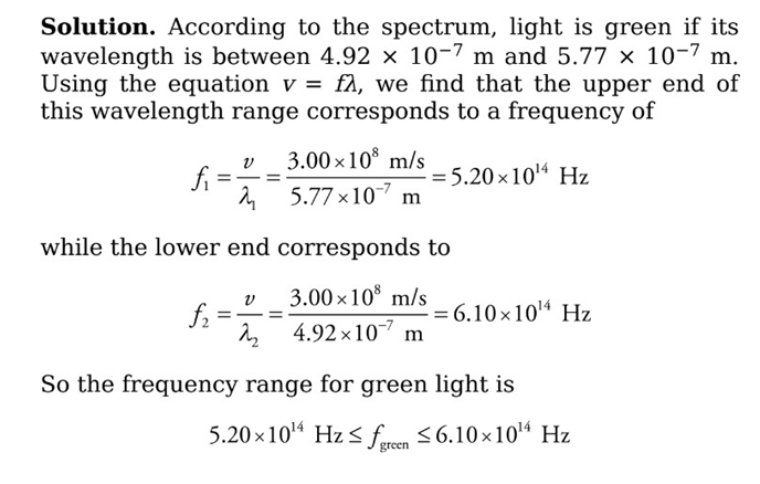
 Example: What is the frequency of green light? (use v = f λ)
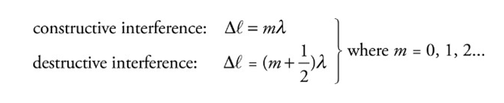
❖ Interference and Diffraction:
➢ The waves experience interference when they meet.
➢ They interfere destructively or constructively depending on their relative phase.
■ They meet in phase (crest meets crest): combine constructively
■ They meet out of phase (crest meets trough): and combine destructively.
➢ Waves are assumed to be coherent (which means their first phase difference remains constant over time and does not vary).
❖ Young’s Double Slit Experiment:
➢ The incident light on a barrier that contains two narrow slits, separated by distance d. On the right there is a screen whose distance from the barrier L, is much greater than d.
 ➢ Diffraction: The alteration in the straight-line propagation of a wave when it encounters a barrier is called diffraction.
➢ The waves will diffract through the slits spread out, and interfere as they travel towards the screen.
➢ Points of interference can be seen:
■ Solid lines: constructive interference
■ Dashed lines: destructive interference


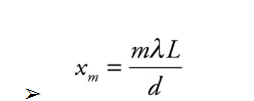 ➢ The intensity of the bright fringes decreases as m increases in magnitude.
➢ Barriers containing thousands of tiny slits per centimeter are called diffraction gratings.
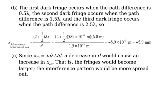
Example: For the experimental set-up we’ve been studying, assume that d = 1.5 mm, L = 6.0 m, and that the light used has a wavelength of 589 nm.
(a) How far above the center of the screen will the second brightest maximum appear?
(b) How far below the center of the screen is the third dark fringe?
(c) What would happen to the interference pattern if the slits were moved closer together?

❖ Single Slit Experiment:
➢ A diffraction pattern will also form on the screen if the barrier contains only one slit.
❖ Reflection and Refraction:
➢ The angle that the incident beam makes with the normal is called the angle of incidence.
➢ The angle that the reflection makes with the normal is called the angle of reflection.
➢ The angle that the transmitted beam makes with the normal is called the
angle of refraction.
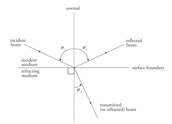
➢ Laws of reflection:
■ The incident, reflection, and transmitted beams of light all lie in the same plane.
■ The relationship between incident and reflected ray:

■ Example: If a light ray incidents on a surface at an angle 60 degree. Then, the angle with which the reflected ray will reflect will also be 60 degree as (angle of incidence = angle of reflection).
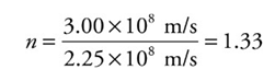
➢ Medium’s index of refraction:
■ n = c/v
■ Example: Since the speed of light in water is v = 2.25 × 10⁸ m/s, the index of refraction of water is
 ➢ Note:
■ n has no units.
■ It is also never less than 1.
■ Light always travels slower in a medium than in a vacuum.
➢ Snell’s law:
■ n 1 sin θ′1 = n2 sin θ′2
■ If n2>n1, the beam will bend/refract towards the normal.
■ If n2<n1, the beam will bend away from the normal.
Example: A beam of light in air is incident upon a piece of glass, striking the surface at an angle of 30°. If the index of refraction of the glass is 1.5, what are the angles of reflection and refraction?

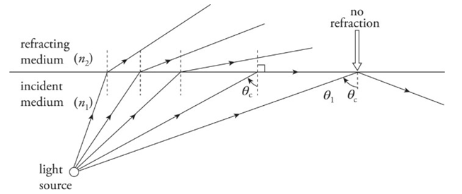
❖ Total Internal Reflection:
➢ When a beam of light strikes the boundary to a medium that has a lower index of refraction, the beam bends away from the normal. As the angle of incidence increases, the angle of refraction becomes larger. At some point, when the angle of incidence reaches a critical angle, θc, the angle of refraction becomes 90°, which means the refracted beam is directed along the surface.
➢ Total internal reflection occurs when:
1) n1> n2 and
2) θ1> θc, where θc = sin−1 (n2/n1)
 ➢ Example: What is the critical angle for total internal reflection between air and water? In which of these media must light be incident for total internal reflection to occur?

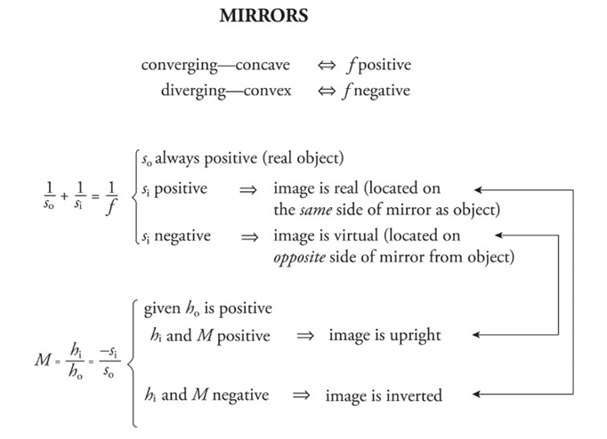
❖ Mirrors:
➢ A mirror is an optical device that forms an image by reflecting light.
❖ Plane Mirror:
➢ Light that is reflected off the mirror and is reflected back to our eyes.
➢ The direction of the rays reflected off the mirror determines where we perceive the image to be.
 ➢ Our image is behind the mirror and stands at an equal distance as we stand before the mirror.
➢ An image is said to be real if light rays actually focus on the image. A real image can be projected onto the screen.
➢ The images produced by the flat mirror are virtual.
➢ In a flat mirror we see an upright image because it's virtual.
➢ In real images the image is upside down.
➢ The image formed by plane mirrors is neither diminished nor enlarged.
❖ Spherical Mirrors:
➢ A spherical mirror is a mirror that’s curved in such a way that its surface forms part of a sphere.
➢ The center of this imaginary sphere is the mirror’s center of curvature.
➢ The radius of the sphere is called the mirror's radius of curvature R.
➢ Halfway between the mirror and the radius of curvature is called the focus.
➢ The intersection of a mirror's optic axis with the mirror itself is called the vertex.
➢ V, and the distance from V to F is called the focal length f, equal to one-half of the radius of curvature.
■ F = R/2
➢ Concave mirror: A mirror whose reflective side is caved in toward the center of curvature.
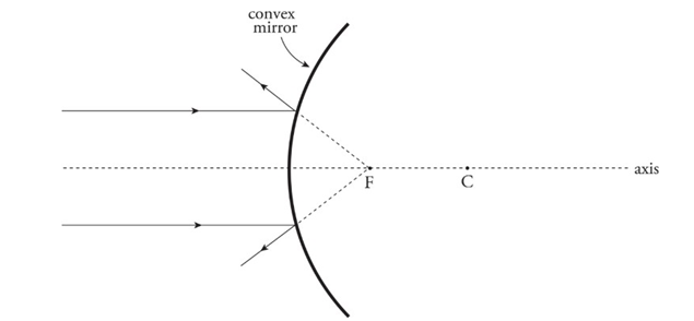
 ➢ Convex mirror: A mirror whose reflective side curves away from the center of curvature.
❖ Ray tracing for the mirrors:
➢ Concave mirrors:
■ An incident ray parallel to the axis is reflected through the focus.
■ An incident ray that passes through the focus is reflected parallel to the axis.
■ An incident ray that strikes the vertex is reflected at an equal angle to the axis.
➢ Convex mirrors:
■ An incident ray parallel to the axis is reflected away from the virtual focus.
■ An incident ray directed toward the virtual focus is reflected parallel to the axis.
■ An incident ray that strikes the vertex is reflected at an equal angle to the axis.
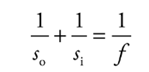
➢ Equations:
■ The mirror equation:
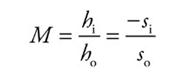
 ■ The magnification equation:
 Example: An object of height 4 cm is placed 30 cm in front of a concave mirror whose focal length is 10 cm.
(a) Where’s the image?
(b) Is it real or virtual?
(c) Is it upright or inverted?
(d) What’s the height of the image?
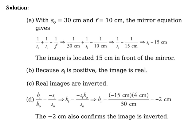
➢ Conclusion:
❖ Thin Lenses:
➢ A lens is an optical device that forms an image by refracting light.
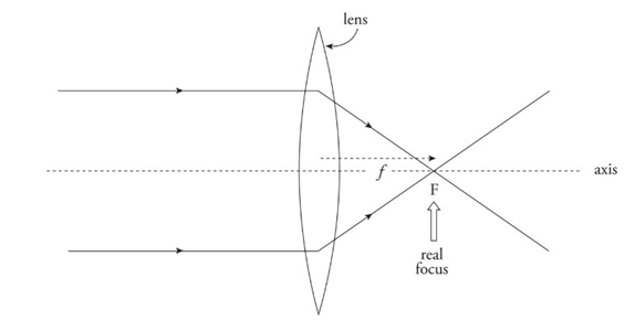
➢ Converging lens: Bi-convex lens
■ Converges parallel paraxial rays of light to a focal point on the far side.
■ Because parallel light rays actually focus at F, this point is called a real focus. Its distance from the lens is the focal length, f.
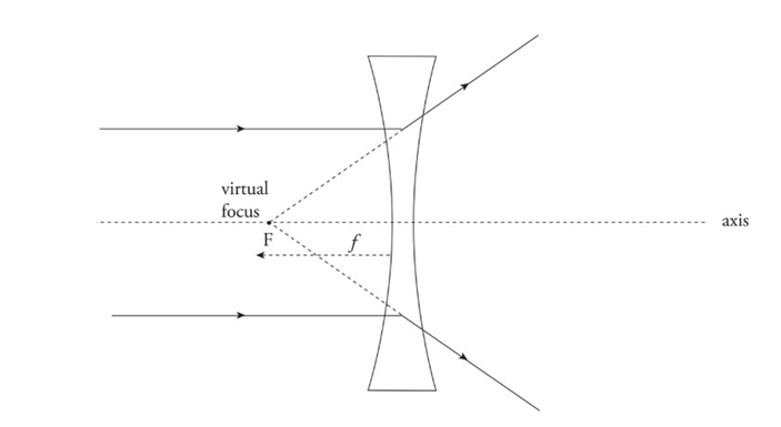
 ➢ Diverging lens: Bi-concave lens
■ Causes parallel paraxial rays of light to diverge away from a virtual focus, F, on the same side as the incident rays.
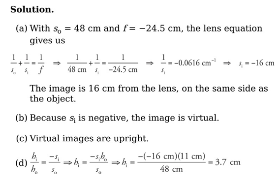
 Example: An object of height 11 cm is placed 48 cm in front of a diverging lens with a focal length of −24.5 cm.
(a) Where’s the image?
(b) Is it real or virtual?
(c) Is it upright or inverted?
(d) What’s the height of the image?
 ➢ Power of Lenses:
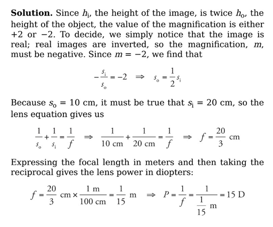
■ The power of a lens, P, is defined as 1/f, where f is the lens’s focal length (in meters). Lens power is expressed in diopters (abbreviated D), where 1 D = 1 m−1.
■ Example: When an object is placed 10 cm from a converging lens, the real image formed is twice the height of the object. What’s the power of this lens?
❖ Ray tracing for lenses:
➢ Converging Lenses:
■ An incident ray parallel to the axis is refracted through the real focus.
■ Incident rays pass undeflected through the optical center, O (the central point within the lens where the axis intersects the lens).
➢ Diverging Lenses:
■ An incident ray parallel to the axis is refracted away from the virtual focus.
■ Incident rays pass undeflected through the optical center, O.