


AQA GCSE Physics Trilogy: Fleming's Left-Hand Rule
The Motor Effect:
The force on a given length of wire in a magnetic field increases when -
The current in the wire increases
The strength of the magnetic field increases
For any given combination of current and magnetic field strength, the force is greatest when the direction of the current is 90° to the direction of the magnetic field
There is no motor effect force if the current and the magnetic field are parallel to each other.
Fleming’s Left-Hand Rule:

The forefinger is lined up with magnetic field lines pointing from north to south
The second finger is lined up with the current pointing from positive to negative
The thumb shows the direction of the motor effect force on the conductor carrying the current
In which direction will this wire feel a force?
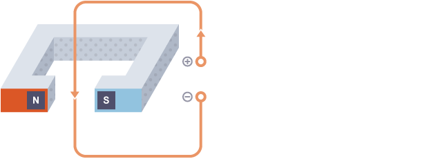
With the forefinger (magnetic field) pointing left to right, and the second finger (current) pointing down, your left thumb (force) will point towards you. This is the direction in which the force acts.
Electric Motors:
A coil of wire carrying a current in a magnetic field experiences a force that tends to make it rotate. This effect can be used to make an electric motor.
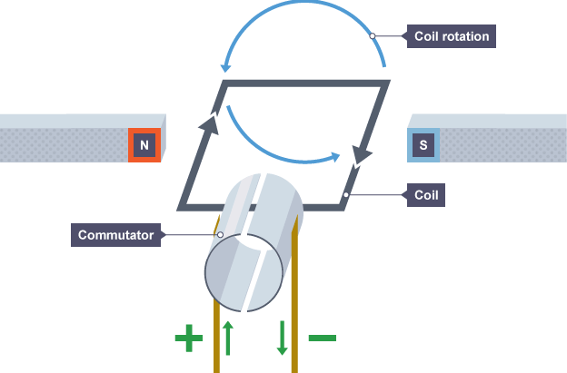
Starting from the position shown in the diagram of the dc motor:
The current in the left-hand part of the coil causes a downward force, and the current in the right-hand part of the coil causes an upward force
The coil rotates anti-clockwise because of the forces described above
When the coil is vertical, it moves parallel to the magnetic field, producing no force. This would tend to make the motor come to a stop, but two features allow the coil to continue rotating:
The momentum of the motor carries it on around a little
A split ring commutator changes the current direction every half turn
Once the conducting brushes reconnect with the commutator after a half turn:
Current flows in the opposite direction through the wire in the coil
Each side of the coil is now near the opposite magnetic pole
This means that the motor effect forces continue to cause the anti-clockwise rotation of the coil.
Transformers:
Transformer - a device that can change the potential difference or voltage of an alternating current.
A step-up transformer increases the voltage.
A step-down transformer reduces the voltage.
Transformers can only work with alternating currents.
A basic transformer is made from two coils of wire, a primary coil from the alternating current (ac) input and a secondary coil leading to the ac output. The coils are not electrically connected; instead, they are wound around an iron core. This is easily magnetised and can carry magnetic fields from the primary coil to the secondary coil.
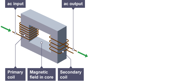
When a transformer is working:
A primary voltage drives an alternating current through the primary coil.
The primary coil current produces a magnetic field, which changes as the current changes.
The iron core increases the strength of the magnetic field.
The changing magnetic field induces a changing potential difference in the secondary coil.
The induced potential difference produces an alternating current in the external circuit.