


Chapter 4: Microscopy
4.1: Magnification Systems
Simple magnification system: A single lens used to form an enlarged image of an object.
A similar system is used to project the image of a 35-mm slide or transparency in a lecture hall.
Compound magnification system – where magnification occurs in two stages and the total magnification is the product of the magnification of the first lens and the second lens.
The observer looks at the first image with a lens that produces an enlarged image called a virtual image.
Real image -- the one that could be seen on the screen—that is, projected onto the screen.
Lens
Lens– a translucent material that bends light in a known and predictable manner.
Focal Length – the distance between the two points of focus on either side of the lens,
Focal length is important in microscopy because it determines much of the image quality.
At 25cm, the resolution, or the minimum distance two objects can be separated and still be seen as two objects, of the human eye is between 0.15 and 0.30mm.
This is the limit of human eyes without assistance; if a better resolution is required, the image must be magnified.
As magnification increases, lens diameter decreases to bend the light more to make a larger image.
Compound Magnifying Systems
A compound microscope employs a magnification system that exceeds the limits imposed by simple lenses.
Lenses of up to 40× can be used in a compound microscope, and higher magnifications are possible with special lenses.
Even lenses in compound microscopes have resolution limits, however, and it is possible to continue to magnify an image but not improve its resolution—this is called empty magnification.
The Microscope
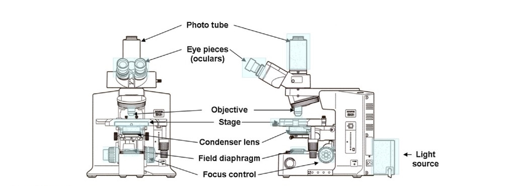
Eyepiece or ocular– the lens that the observer looks into when viewing an object microscopically.
A microscope may be:
Monocular – having one eyepiece, or;
Binocular – having two eyepieces; most found microscopes in laboratories.
Trinocular – three eyepieces; they also have an eyepiece that accommodates a video or digital camera.
The eyepiece(s) will have a magnification of 10× and may be focusable; this allows the viewer to adjust the eyepieces if one eye is stronger than the other. The area seen when looking through the eyepieces is called the field of view and will change if the specimen is moved or the magnification is changed.
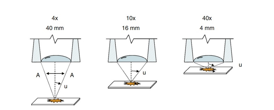
Objective Lens – the most important part of the microscope.
Objectives come in many types and magnifications (typically, 4×, 10×, 15×, 20× and 25×; higher magnifications are possible).
Numerical Aperture – an angular measure of the lens’s light-gathering ability and, ultimately, its resolving quality.
Tube length – the distance from the lowest part of the objective to the upper edge of the eyepiece; this has been standardized at 160mm in modern microscopes.
The microscope stage is the platform where the specimen sits during viewing. The stage can be moved up or down to focus the specimen image, meaning that a portion of the specimen in the field of view is sitting in the same horizontal plane; typically, stages are equipped with a coarse and fine focus.
Condenser – used to obtain a bright, even field of view and improve image resolution.
These are lenses below the stage that focus or condense the light onto the specimen field of view.
They also have their condenser diaphragm control to eliminate excess light and adjust for contrast in the image.
Field diaphragm – a control that allows more or less light into the lens system of the microscope.
Critical Illumination– concentrates the light on the specimenwith the condenser lens; this produces intense lighting that highlights edges but may be uneven.
Köhler illumination – named after August Köhler in 1893, sets the light rays parallel throughout the lens system, allowing them to evenly illuminate the specimen.
It is considered the standard setup for microscopic illumination.
Lens Corrections
Achromatic objectives are the least expensive objectives, and they are found on most microscopes.
These objectives are designed to be corrected for chromatic aberration, where white light from the specimen is broken out into multiple colored images at various distances from the lens.
A simple lens focuses a flat specimen on a microscope slide onto the lens, a rounded surface – curvature of the field.
Regular achromats lack correction for flatness of field, but recently most manufacturers have started offering flat-field corrections for achromat objectives, called plan achromats.
Astigmatism – or spherical aberration results from a lens not being properly spherical. This makes specimen images seem to be “pulled” in one direction when focusing through it.
Fluorites – or semi-apochromats are corrected for spherical aberration, where the light passing near the center of the lens is less refracted than the light at the edge of the lens.
Apochromats – contain several internal lenses that have different thicknesses and curvatures in a specific configuration unique to apochromats.
Infinity-Corrected Lens – produce very high-quality images and allow for the addition of a variety of analytical components to the microscope.
Refractive Index
The refraction of visible light is an important characteristic of lenses that allows them to focus a beam of light onto a single point.
Refraction– occurs as light passes from one medium to another when there is a difference in the index of refraction between the two materials, and it is responsible for a variety of familiar phenomena such as the apparent distortion of objects partially submerged in water.
Refractive Index – the relative speed at which light moves through a material concerning its speed in a vacuum.
Material | RI |
|---|---|
Air | 1.0008 |
Water | 1.330 |
Ice | 1.310 |
Glass | 1.510 |
Diamond | 2.417 |
Ruby | 1.760 |
When light passes from a less dense medium (such as air) to a more dense medium (such as water), the speed of the wave decreases.
When light passes from a more dense medium (water) to a less dense medium (air), the speed of the wave increases.
4.2: Polarized Light Microscopy (PLM)
Polarizing light microscope – exploits optical properties of materials to discover details about the structure and composition of materials, and these lead to its identification and characterization.
Isotropic Materials – demonstrate the same optical properties in all directions, such as gases, liquids, and certain glasses and crystals.
Anisotropic Materials– have optical properties that vary with the orientationof the incoming light and the optical structure of the material. 90% of all solid materials.
A PLM uses two polarizing filters: polarizers and analyzers.
Polarizer – a special filter used when the light passes through it, the only light that passes is that which vibrates in that “preferred” direction.
Polarized Light – light that vibrates in one direction.
Analyzer – It is a device used to determine whether the light is plane polarized or not.
Located above the objectives, it can be manually slid into or out of the light path.
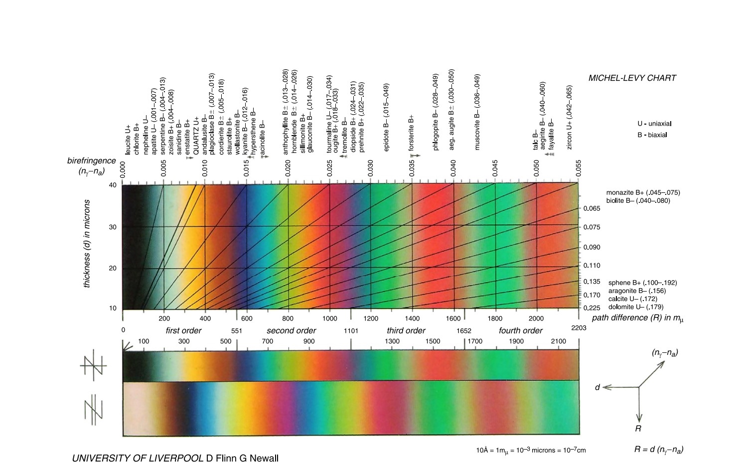
Birefringence – the result of this division of light into at least two rays (the ordinary ray and the extraordinary ray) when it passes through certain types of material, depending on the polarization of the light.
Interference Colors – the wavelengths being added and subtracted through interference; these colors are caused by the interference of the two rays of light split by the anisotropic material interfering destructively with each other.
Michel-Levy Chart – a chart of diameter, birefringence, and retardation. Named after Auguste Michel-Lévy – a French geologist who was born in Paris and became inspector-general of mines and director of the Geological Survey of France.
4.3: Other Microscopical Methods
Fluorescence Microscopy
Fluorescence– luminescence of a substance excited by radiation.
Luminescence can be subdivided into phosphorescence — which is characterized by long-lived emission, and fluorescence — in which the emission stops when the excitation stops.
In a fluorescence microscope, the specimen is illuminated with light of a short wavelength. Part of this light is absorbed by the specimen and re-emitted as fluorescence.
To enable the comparatively weak fluorescence to be seen the light used for excitation is filtered out by a secondary filter placed between the specimen and the eye.
This filter should be fully opaque at the wavelength used for excitation, and fully transparent at longer wavelengths to transmit the fluorescence.
The fluorescent object is therefore seen as a bright image against a dark background.
Electron Microscopy
Electron microscopy employs a particle beam of electrons focused on magnetic lenses.
It does have a much higher resolving power and greater depth of field than light microscopes and can magnify a specimen hundred of thousands of times.
Transmission electron microscope (TEM)
The electron beam passes through a specimen that has been very thinly sectioned and projects the beam onto a specially treated plate that transmits the image to a monitor.
TEM images are much like light microscope images in that they provide information about the internal structure of the specimen.
Scanning electron microscope (SEM)
It rasters a beam of electrons across a specimen and provides a non-colored image of its surface.
SEMs are used in forensic laboratories to analyze a wide variety of samples, including paint, particles, fractures, tool marks, and gunshot residue.
Back-scattered electron detector (BSED)
Detects elastically scattered electrons
Energy-dispersive spectrometer (EDS)
Used technique for elemental analysis and chemical composition determination, associated with electron microscopy.
Wavelength-dispersive spectrometer (WDS)
Measures the wavelength of the emitted radiation using a tightly spaced crystal lattice. The wavelength and the lattice spacing are related using Bragg’s law. It can only detect one wavelength at a time.