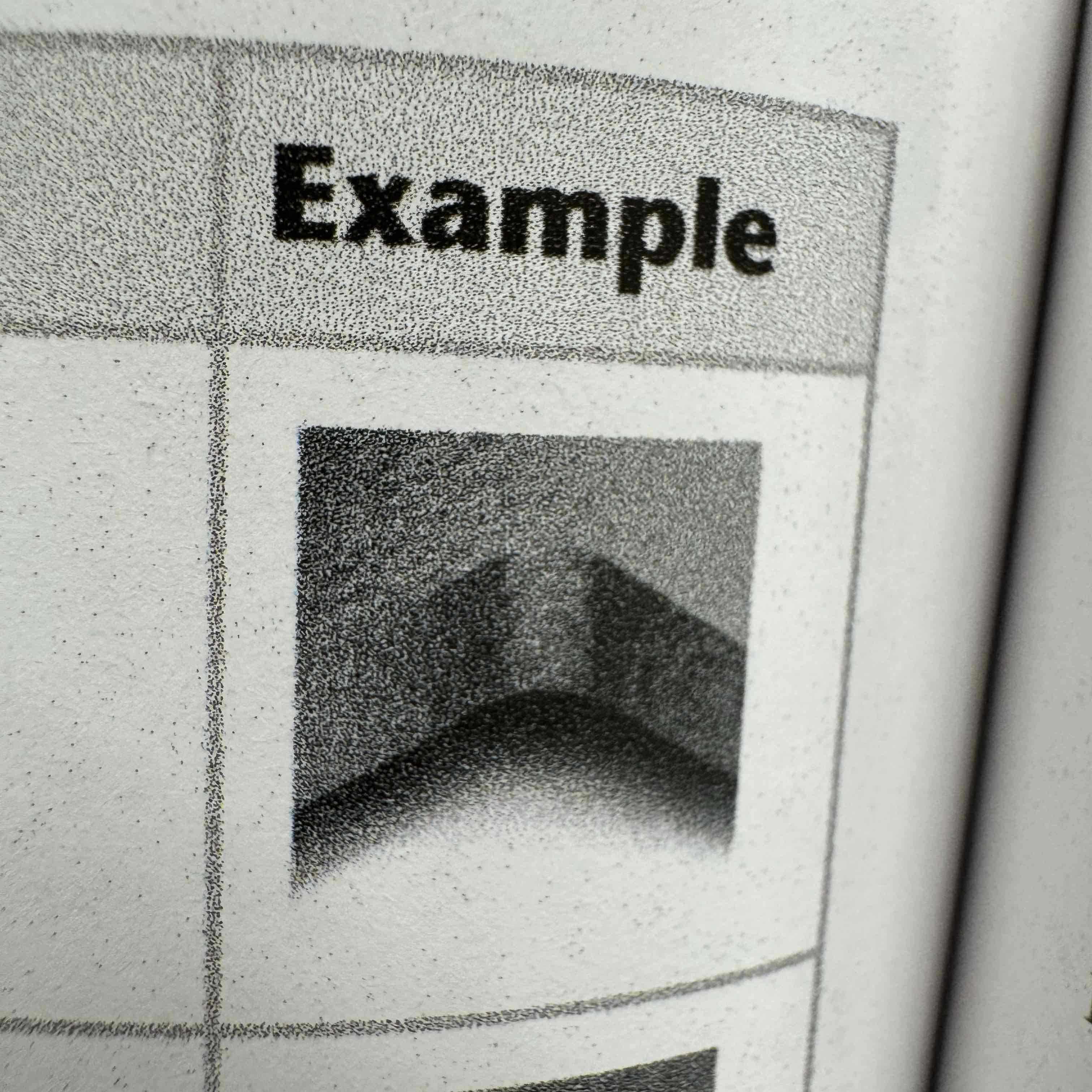
Fillet
A round interior blend between surfaces
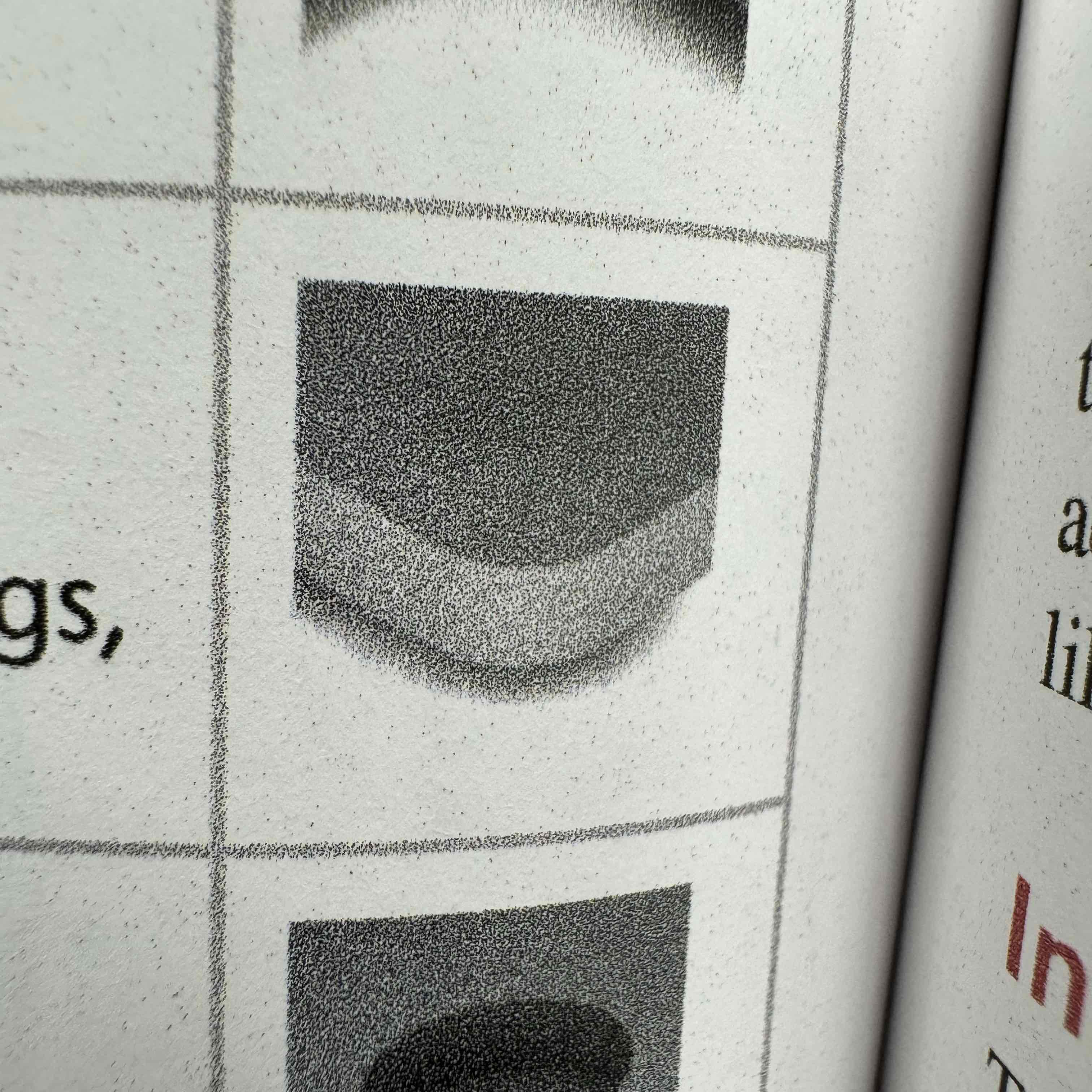
Round
A round exterior blend between surfaces
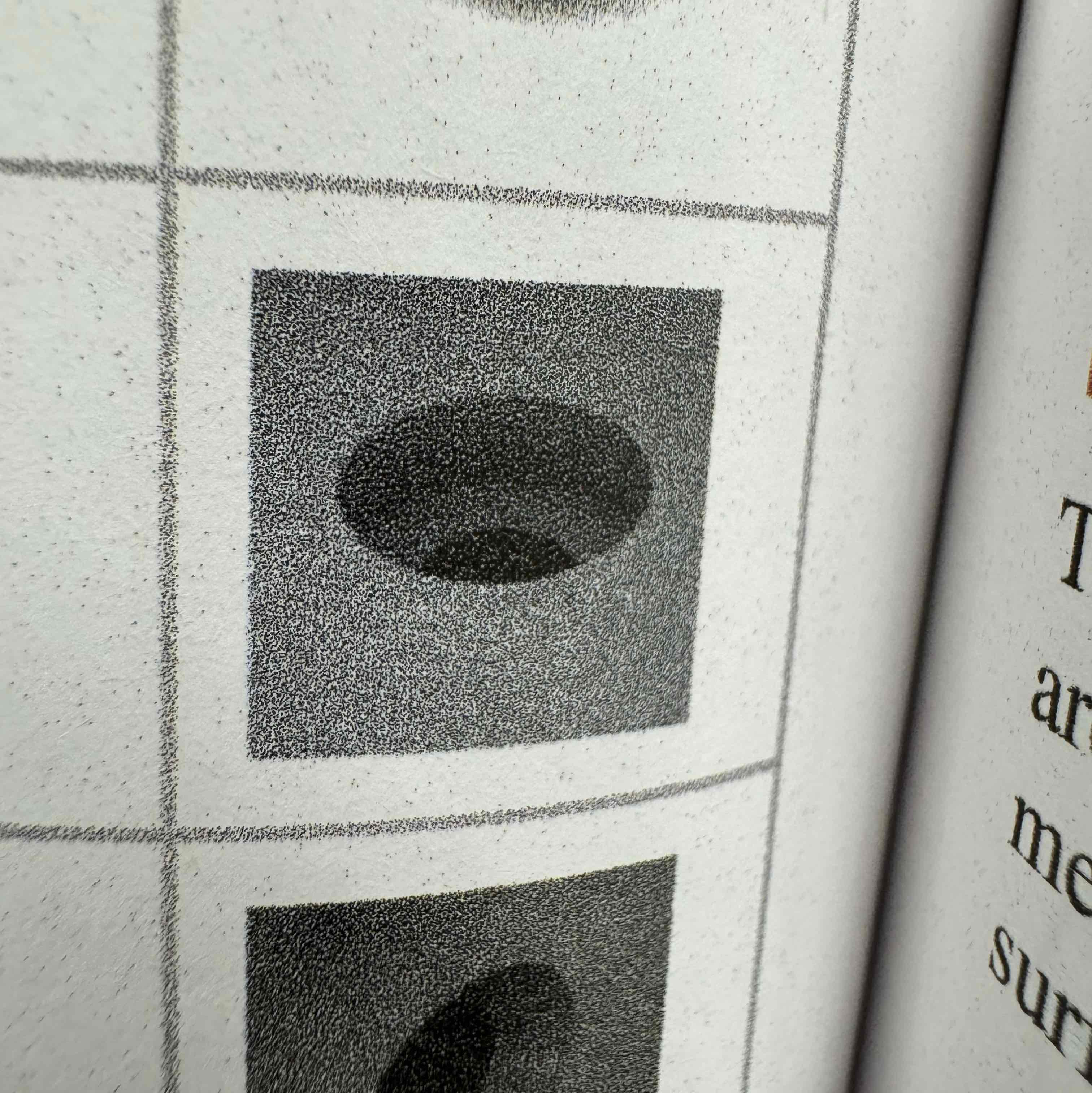
Counterbore
A cylindrical recess around a hole
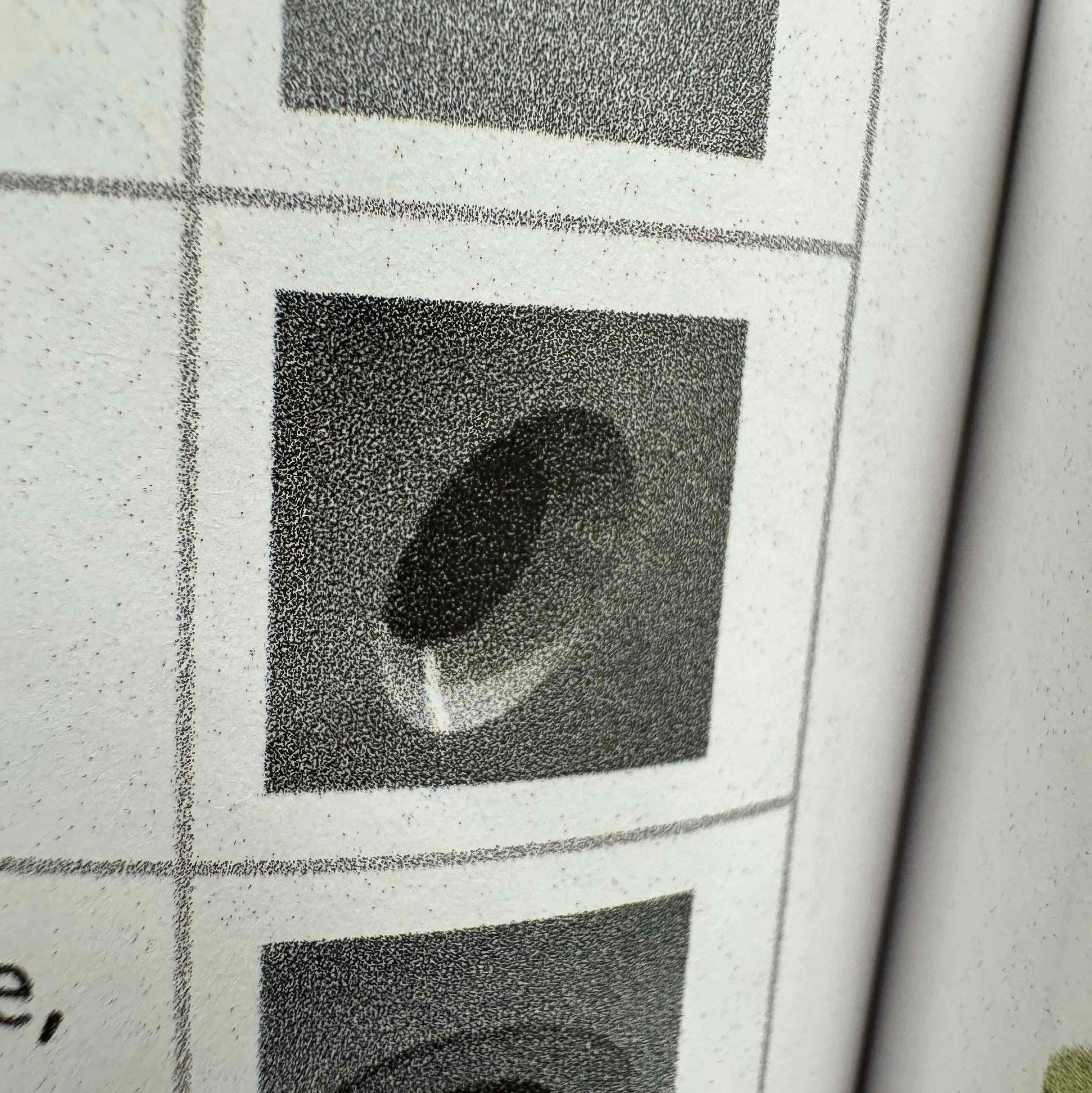
Countersink
A cone-shaped recess around a hole
Flange
A flattened collar or rim around a cylindrical part to allow for attachment
Chamfer
An angled surface
Keyway/Keyseat
A shaped depression cut along the axis of a cylinder
Knurl
A pattern on a surface to provide better gripping
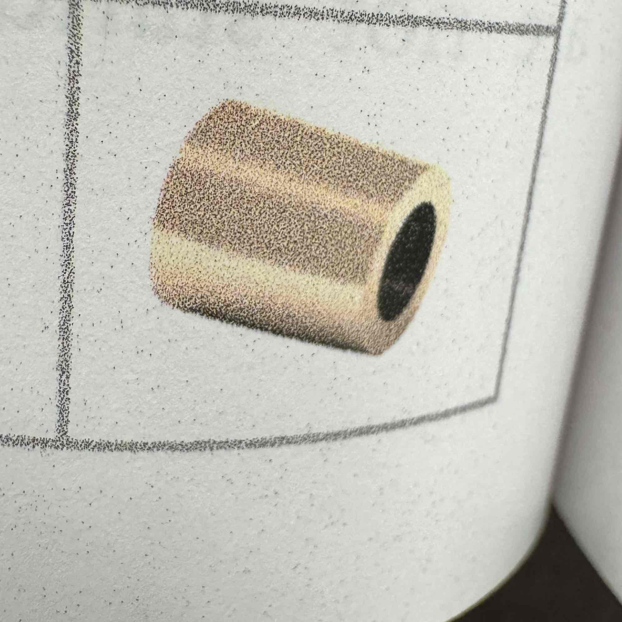
Bushing
A hollow cylinder used as a protective sleeve or guide
Removed view
Complete or partial view removed to another place on the sheet so that it is no longer in direct projection with any other view
Left hand part/ right hand part
two part are mirror images and are not interchangeable; LH part shown, RH opposite
Section Views purpose
To document the design and manufacture of single parts that are manufactured as one piece
To document how multiple parts are to be assembled or built
To aid in visualization the internal workings of a design
Full section
When the part is cut in half
Cutting plane
Cut up or left
Line precedence
When a cutting plane line coincides with a centerline
Broken out sections
Partial section of a view is all that is needed to expose interior shapes (take a bite)
Partial section
Only a portion of the section view is drawn
Removed section
Not direct projection from the view of the cutting plane
Rotation arrow
Used when you just rotate the view
Projection
View of an object
Three principle dimensions
Width, height, and depth
Plane of projection
Sheet of glass parallel to the front surfaces of the object
Glass Box
Views on the sheet of paper is to envision a glass box
Spacing between views
Views should be spaced well apart but close enough to appear related to each other
Three regular views
Top, front, right-side
Centerlines
Show the axis of symmetry for a feature or part
Indicate a path of motion
Show the location for bolt-hole circles and other circular patterns
Precedence of Lines
A visible line always takes precedence over and covers up a centerline or a hidden line when they coincide in a view
Normal Surface
Parallel to a plane of projection
Inclined surface
Perpendicular but inclined to adjacent plane
Oblique Surface
Tipped to all principle planes of projection
Aligned Sections
When parts with angled elements are sectioned
Ortho
90, F8
Osnap
Object snap, F3
UPS
Uninterrupted power system
Half section
Exposed interior half of object and exterior of the other half
Rules for lines in section views
Show edges and contours that are now visible behind the cutting plane
Omit hidden lines in section views
Hidden lines are necessary for clarity
Sectioned area is completely bounded by a visible outline
Section lines in all hatched areas must be parallel
A visible line can never cross a sectioned area in a view of a single part